Introduction
The iron carbon phase diagram is, without doubt, the most used diagram in material science. Those in the industry rightly refer to it as the “Monalisa” of material science.
Students learn it in the very first year of their engineering courses and use it for the rest of their lives if they choose to pursue metallurgy.
In this article, we try to simplify the iron carbon phase diagram as much as possible by explaining every term while not losing sight of the big picture. Let us begin.
What is the Iron Carbon Phase diagram?
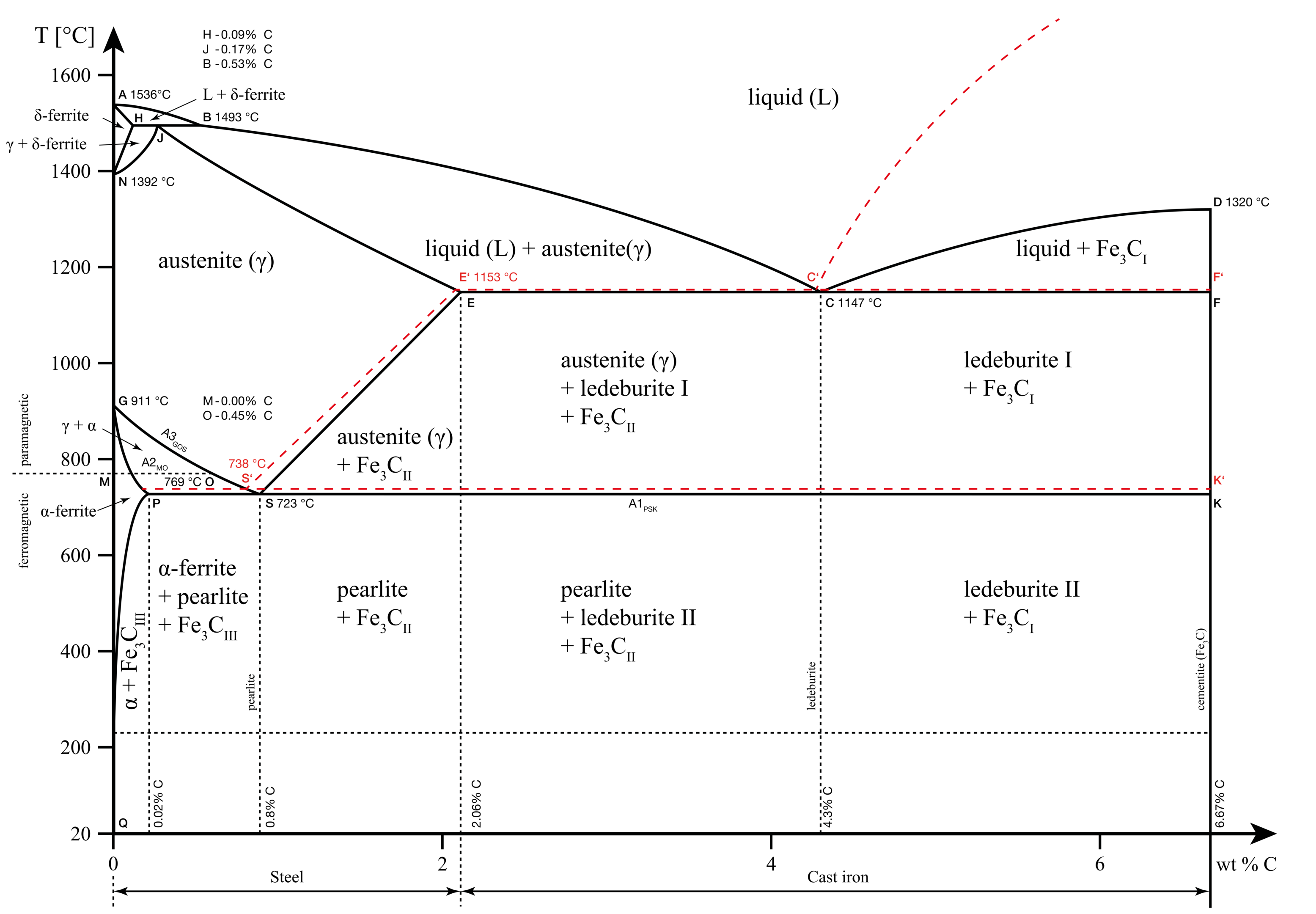
The iron-carbon phase diagram is an equilibrium diagram that explains the phases or microstructure of iron carbon alloys (carbon steels and cast irons) at different temperatures and carbon percentages.
On the X-axis, we have the carbon concentrations from 0% to 6.67%. On the Y-axis, we have the temperature of the phase, ranging from 0°C (32°F) to 1650°C (~3000°F).
The area between the axes shows the existence of different phases in different regions. Using the diagram, we can take the intersection of a specific temperature and percentage of carbon to understand the phases present at that point.
What is the significance of these phases? Each phase has a different microstructure that provides it with different mechanical properties such as strength, hardness, durability and so on.
The different applications of materials science require different combinations of properties from cast iron and carbon steels. By using phase diagrams, we can obtain desired properties in plain carbon steels and cast irons through heat treatment.
Pure iron and its allotropes
Iron is the second most abundant metal in the earth’s crust after aluminium. But pure iron is extremely soft and brittle. This reduces its weight-carrying capacity and therefore, its direct usage in applications.
The melting temperature of pure iron is 1536 °C (2796.8 °F). Above this temperature, iron exists in a homogenous liquid phase. We refer to this phase as ‘Melt’ in the iron-carbon phase diagrams.
Iron is also one of the few polymorphous metals. This means that the iron molecule can exist in different crystal structures or allotropes at different temperatures. Let us understand the three main allotropes of iron.
- Delta iron
- Gamma iron
- Alpha iron
Delta iron
Pure iron melts at 1536 °C. Above this temperature, iron exists in a homogenous liquid phase. When the temperature of the melt falls below 1536 °C, the first arrest point occurs, the melt solidifies and we obtain the first allotrope of iron known as the delta iron.
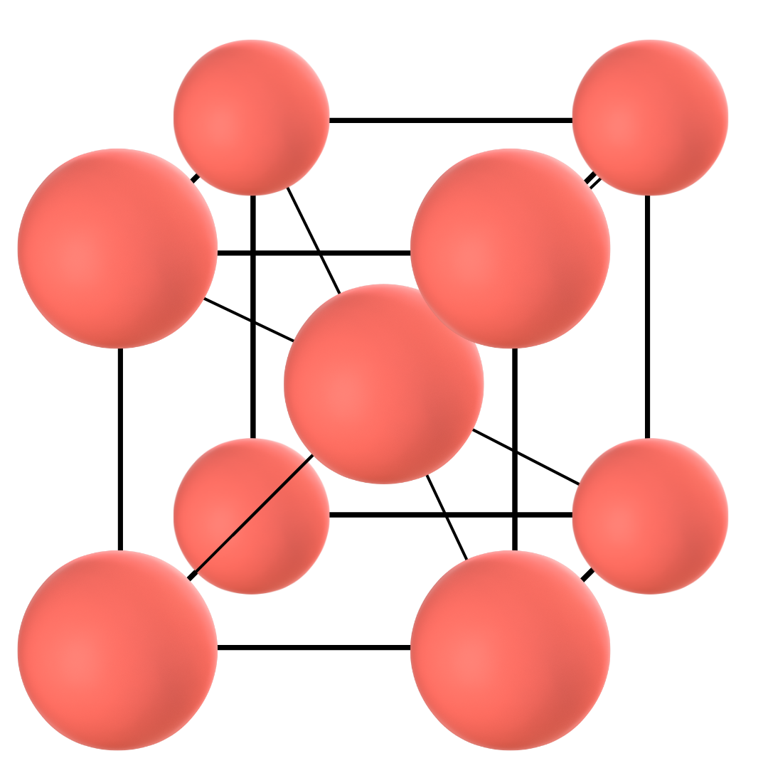
Delta iron has a body-centred cubic (BCC) crystal structure. This means that a sample cube of the atom arrangement in the structure consists of a full molecule at the centre and 1/8th molecule at each of the eight edges. It is the least densely packed of all the three allotropes. In other words, it consists of more empty spaces than other allotropes of iron.
Gamma iron
When the temperature of pure iron falls below 1401 °C, the second arrest point occurs and the allotrope of iron known as Gamma iron appears. Note that this is a solid-to-solid phase transformation (Delta to Gamma iron) that is exothermic in nature, i.e. the transformation gives out heat.
Gamma iron has a face-centred cubic structure. This means that a sample cube of the atom arrangement in the structure will have one-half of the atom on each of the six faces and 1/8th on each of the eight corners.
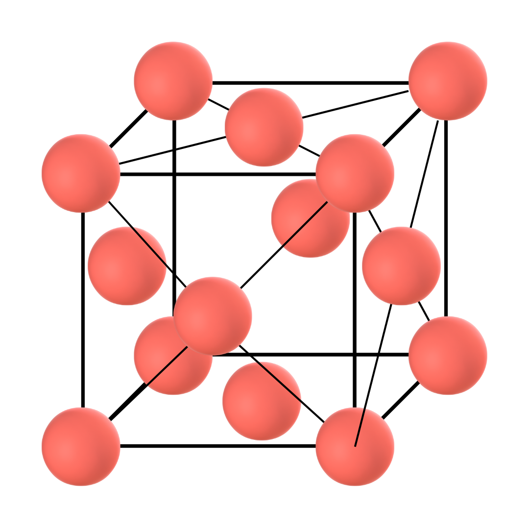
As can be understood by the atom distribution, this allotrope is more densely packed than Delta iron. This phase is also known as Austenite. Thus, whether pure or mixed with alloying elements such as carbon, the phase is known as Gamma iron or Austenite.
Alpha iron
This is the third allotrope of iron that materializes when the temperature of pure iron drops below 911 °C. Alpha iron also occurs through a solid-to-solid formation and is the allotrope that can exist at room temperature. Alpha iron is also known as ferrite.
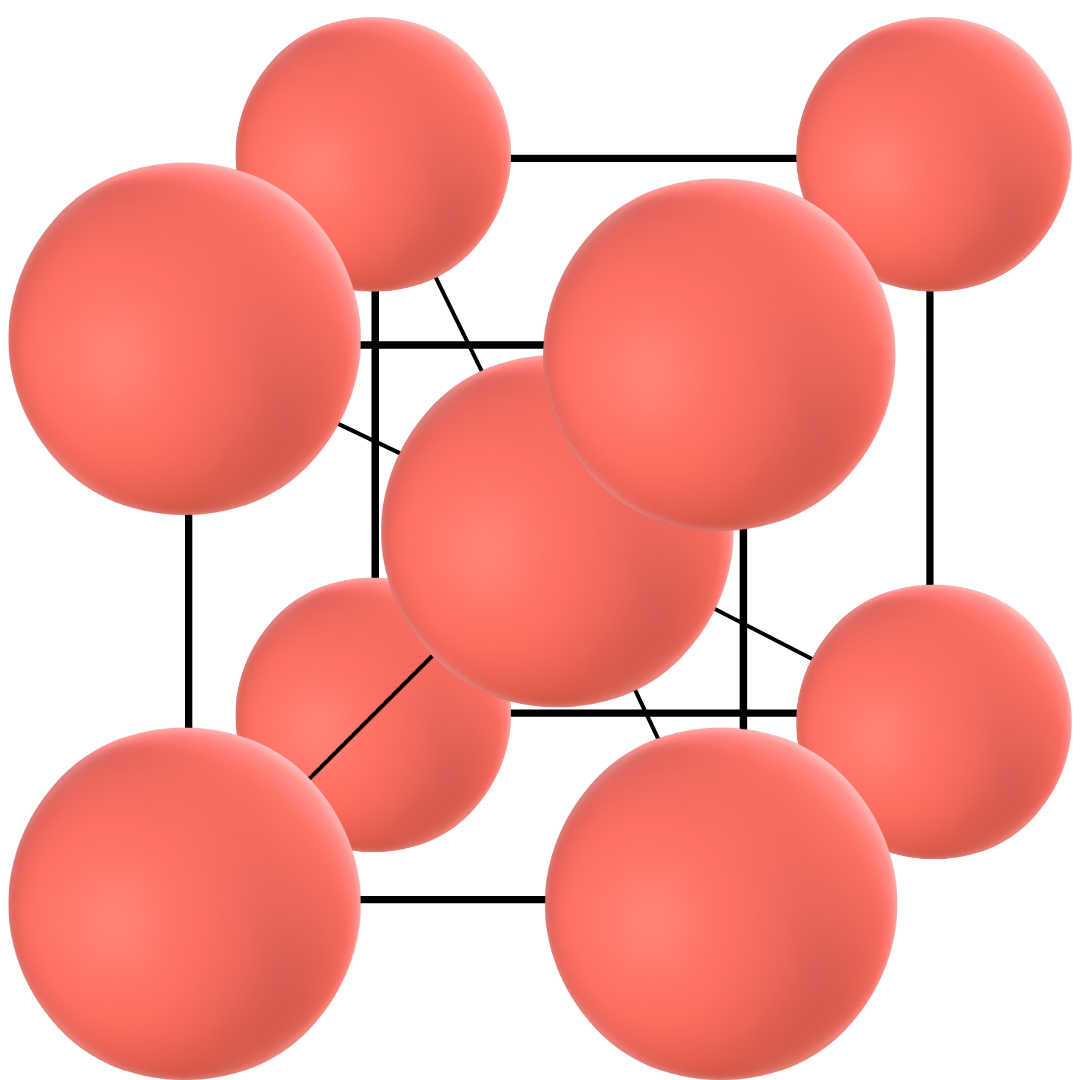
Ferrite has a body-centred cubic structure like delta iron but it has smaller lattice constants. In simple terms, lattice constants refer to the amount of empty space in a crystal structure and thus, the alpha iron is more densely packed than the delta iron.
Alpha iron has the largest temperature range and exists right down to room temperature. But below a certain temperature, the material regains its lost magnetic property.
This temperature is known as the Curie temperature, named after Pierre Curie, who proved that some materials lose their permanent magnetism above a specific temperature.
For pure iron, this temperature is 770 °C. Above this temperature, the iron is paramagnetic. Alpha iron or ferrite becomes magnetic once its temperature drops below 770 °C. The phase between 770 and 911 °C was known as beta iron before and the two phases are separated by the A2 line in the iron-carbon equilibrium diagram.
Steel and cast iron
Pure iron has many undesirable properties that make it unfit for most applications. But the addition of carbon can change that.
Carbon imparts so many amazing properties to iron that carbon steel and cast iron are how we use the majority of iron ore. In this section, let us understand each of these.
Plain Carbon Steel
Plain carbon steels are steels produced by the addition of carbon to pure iron. When other alloying elements are also used (e.g. chromium, molybdenum, etc.), the steel is known as alloy steel.
Carbon steel contains low carbon content between 0.008% and 2.14%. Based on the carbon percentage, carbon steels are divided into three main types: Low carbon steels, Medium carbon steels and High carbon steels.
Low-carbon steels contain carbon between 0.008% and 0.30% carbon. Medium-carbon steels contain between 0.30% and 0.60% carbon. The remaining steels that contain more than 0.60% carbon are referred to as high-carbon steels. With increasing carbon content, steel increases in strength and hardness.
Cast iron
Cast iron consists of greater carbon content than carbon steels. However, most popular cast irons contain between 2.5% and 4.0% carbon. Increased carbon content makes cast iron more brittle which make it unsuitable for forging.

Lines in the Iron Carbon phase diagram
Liquidus line
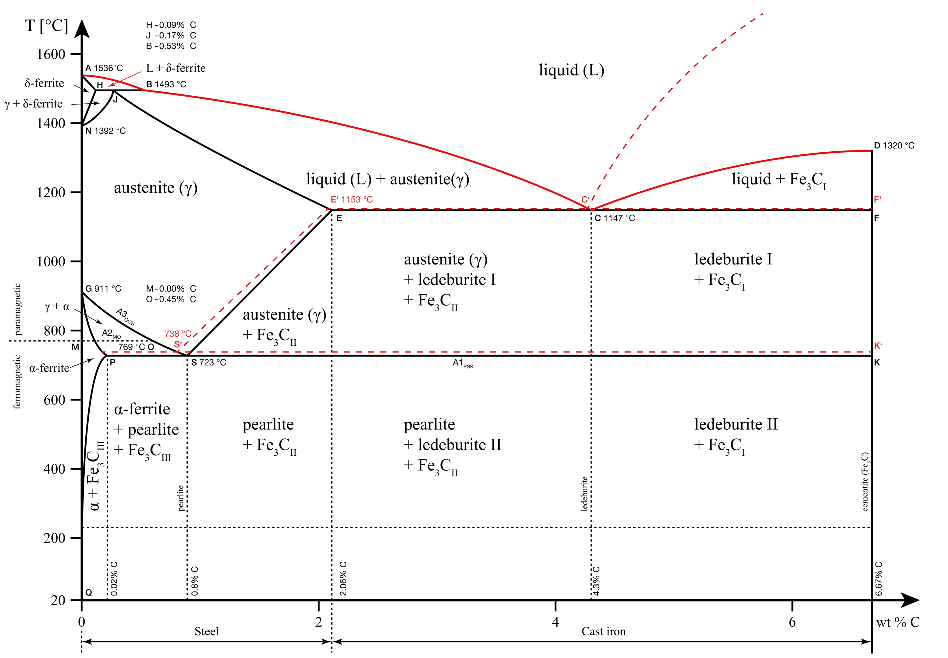
The liquidus line in our iron-carbon phase diagram is the line formed by points A, B, C, and D. Above this line, the alloy exists in the liquid phase.
Solidus line
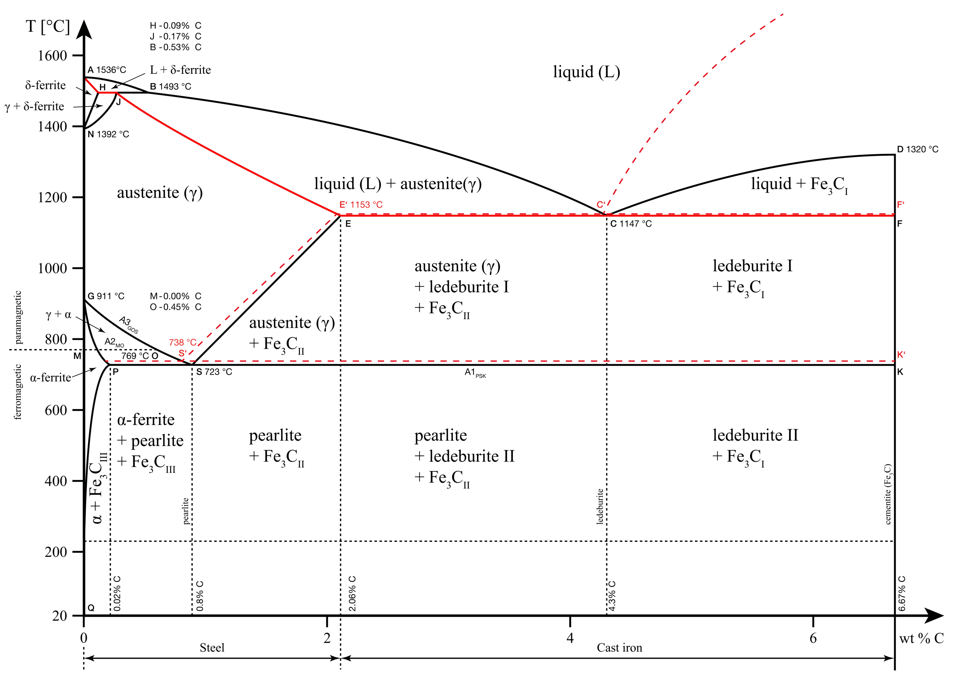
The solidus line in our iron-carbon phase diagram is the line formed by points A, H, J, E, C, and F. Below this line, the metal exists as a solid solution that is completely rigid. Any transformations below this point are a solid-to-solid phase transformation.
A1, A2, A3, Acm lines
A in these lines refers to the word ‘arrest’. These lines denote the arrest points at different carbon content. We know from earlier sections that arrest points are points where the phase change occurs. Thus, these are the points where iron changes phases either by absorbing or rejecting heat.
This phenomenon where the heat transfer occurs without a change in temperature is known as thermal arrest. Hence, the name A1, A2, A3 and Acm.
Important points in the iron carbide diagram
The lines discussed above form various important points throughout the iron carbide diagram. These points are important sites where specific reactions occur. The three important points that we will discuss in this section are as follows:
- Eutectic point
- Eutectoid point
- Peritectic point
Eutectic point
An eutectic system is one in which the mixture of two or more elements has a lower melting point than either of the constituents. All the constituents melt simultaneously at this temperature.
This is different from the case of a non-eutectic mixture in which each of the constituent’s lattice structure melts at different temperatures.
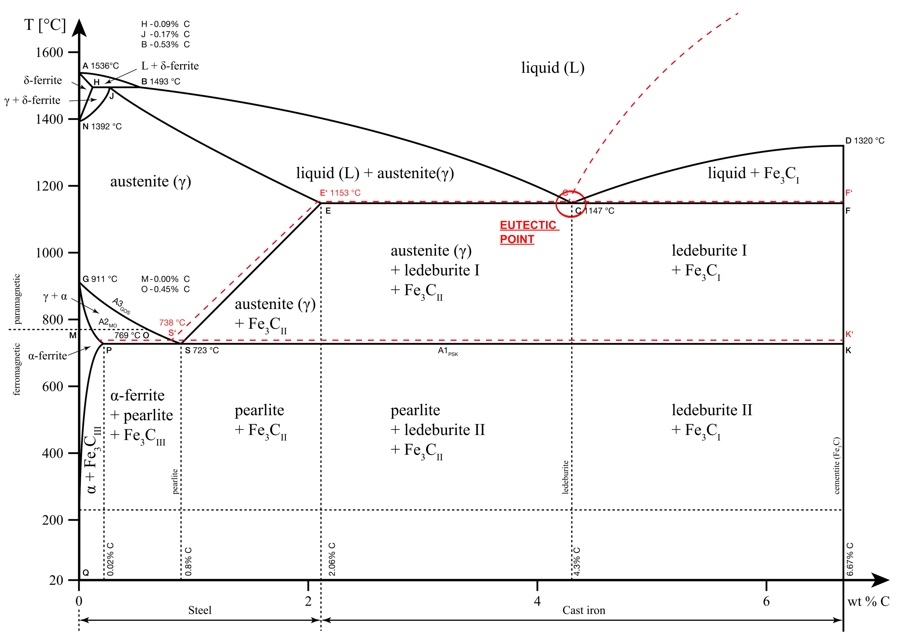
For the iron-carbon solution, the eutectic point occurs at 4.3% carbon concentration and 1147 °C. At this point, further cooling converts the liquid melt to a solid mixture of two solid phases: Austenite and Cementite. This phase is also known as Ledeburite.
Eutectic reaction: L (4.3% C) = γ(2.14% C) + Fe3C
When the carbon concentration reduces, the solution is known as hypoeutectic and when it increases, the solution is known as hypereutectic.
Eutectoid point
The eutectoid point in the iron-carbon diagram occurs at 0.76% Carbon and 727 °C. At this point, Austenite converts into Alpha ferrite and Cementite. The resultant phase mixture is also known as pearlite. This is a solid-to-solid transition and at the eutectoid point, all three solid phases coexist.
Eutectoid reaction: γ (0.76% C) = α (0.022% C) + Fe3C
When the carbon concentrations fall below 0.76%, the solution is known as hypoeutectoid and when it increases above 0.76%, the solution is known as hypereutectoid.
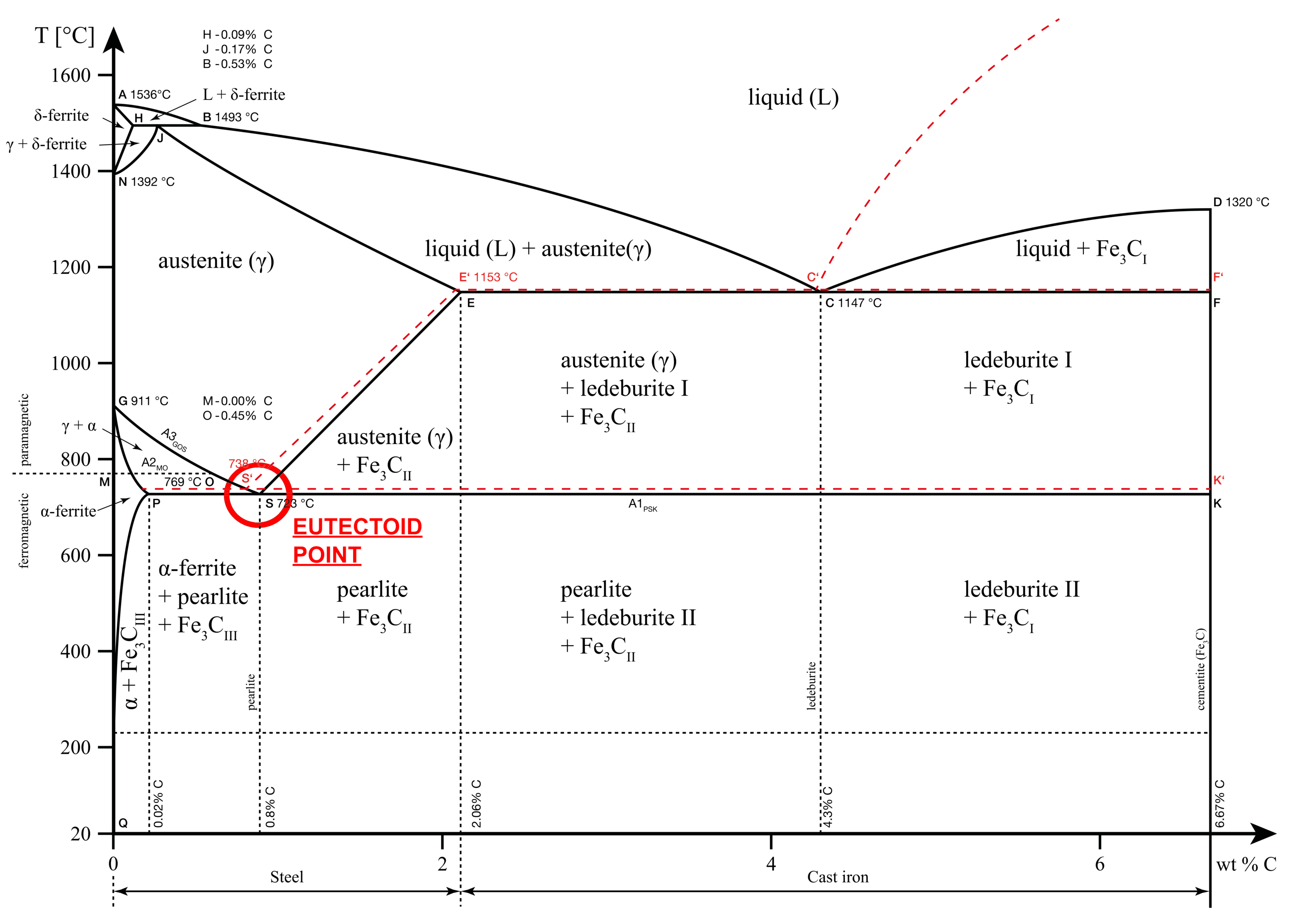
The hypoeutectoid chemical composition results in more ferrite and less pearlite on cooling. On the other hand, a hypereutectoid composition results in cementite and pearlite.
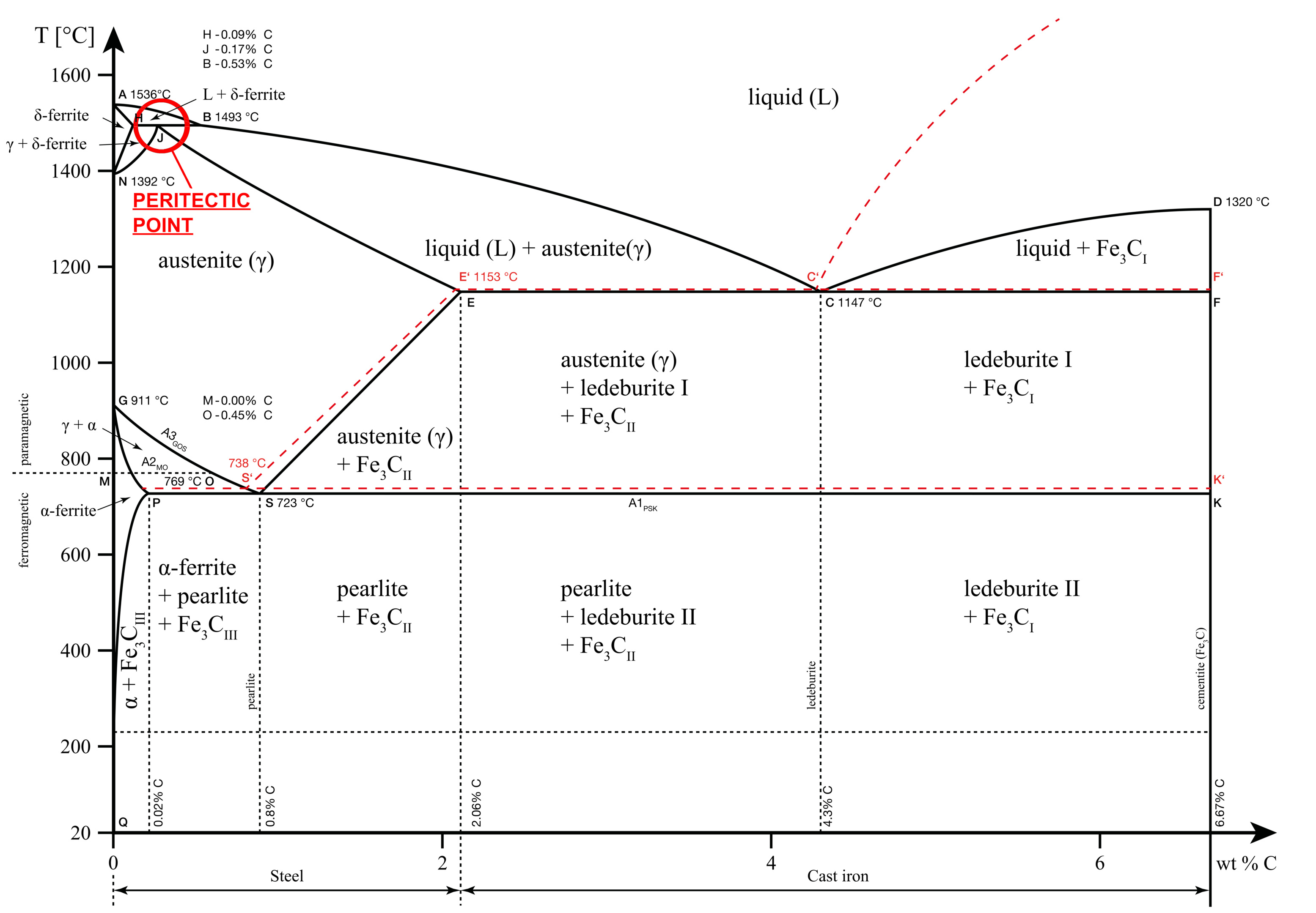
Peritectic point
The peritectic point in the iron carbide diagram occurs at 0.16% Carbon and 1493 °C. In this reaction, the liquid melt and the δ iron convert into austenite.
Peritectic reaction: δ (0.11% C) + L (0.51% C) = γ(0.16%C)
The peritectic point is not of much significance to material scientists as it occurs at very high temperatures and few heat treatment processes are performed at these temperatures.
Types of iron phases with carbon
Iron forms different phases with carbon at varying temperatures and concentrations. As we saw earlier, the different allotropes occur at different temperatures. Those temperatures are for pure iron. As we increase/decrease the carbon content, the transformation temperatures change.
For example, the line A3 in our iron-carbon phase diagram shows the change from γ to α-iron. The line slopes downward which confirms that as we introduce carbon, the transformation temperature reduces.
In this article, let us get a brief understanding of the different phases.
Austenite and Ferrite
Austenite (γ-iron) and ferrite (α-iron) are pure iron phases as discussed earlier in the article. These phases are also formed when carbon is introduced but only up to a certain extent.
Cementite
Cementite or iron carbide is an intermediate phase of iron with carbon. It consists of 93.3% iron and 6.69% carbon. It has an orthorhombic crystal structure that is hard and brittle. Cementite is also magnetic up to a temperature of 215°C.
The ferrite phase can have a maximum solubility of 0.02% carbon by weight. So, as we cool carbon steels and cast irons, a portion of the mixture turns into cementite. Cementite also exists in three different forms, namely Cementite I, Cementite II and Cementite III.
Pearlite
Pearlite is the exact concentration of the solid phase below the eutectoid temperature and concentration (727°C, 0.76%C). It is formed when austenite is cooled slowly below the eutectoid temperature.
It has alternating layers of ferrite and cementite. As we move to the left of the vertical line drawn from the eutectoid point to the X-axis, the concentration of pearlite and cementite reduces and that of ferrite increases.
On the other hand, as we move to the right of this line, the ferrite phase disappears and only pearlite and cementite remain in the solid solution.
Ledeburite
Ledeburite is the exact concentration of the iron carbon alloy at the eutectic composition and temperature (4.3%C, 1147°C). It consists of an eutectic mixture of austenite and cementite. As we move down from this point, we have a pure ledeburite solution.
On the left of this line, austenite concentration increases and cementite concentration decreases. On the right, cementite concentration increases and austenite disappears.
Martensite
Martensite is a phase of the iron-carbon alloy which is formed when austenite is cooled rapidly to low temperatures. The phase is not shown in the iron-carbon equilibrium diagram because it is not an equilibrium phase. Equilibrium phases occur through diffusion that takes place under slow cooling rates which is not how martensite forms.
Bainite
Bainite is an intermediate phase between fine-pearlite and low-temperature martensite. It is formed when carbon steels undergo accelerated cooling but not as fast as martensite. The cooling is, however, faster than that required for pearlite formation.
Bainitic steels offer a good combination of high strength, good weldability and creep resistance. As a result, they have been used in the power generation industry for decades.
